- Inspire
- Innovate
- Integrate

- Home
- Case Studies
- HVAC Acoustic Noise Control Case Study in Luxury Hotel Multipurpose Hall: Root Cause Analysis & Cost-Effective HVAC Noise Mitigation
HVAC Acoustic Noise Control Case Study in Luxury Hotel Multipurpose Hall: Root Cause Analysis & Cost-Effective HVAC Noise Mitigation
Project Snapshot
Parameter | Detail |
Client | Brand Hotel |
Sector | Hospitality |
Location | United Arab Emirates (Dubai) |
Platform / Software | Sound Level Meter, NTI Room Acoustics Reporter, Analytical Calculation |
Standards | 2023 ASHRAE Handbook, Chapter 49. Noise & Vibration Control |
Service | Conserve Solutions – Acoustics division |
Key Outcome for | HVAC-related noise in the multipurpose hall was analysed, root cause identified, and a cost-effective acoustic solution implemented, achieving compliance with the employer’s NC 35 requirement. |
Problem Statement
During the acoustic testing stage of a luxury hotel project in Dubai, the multipurpose hall exceeded 9 NC (≃ 14 dBA) from the employer’s HVAC maximum noise requirement (Noise criteria) of NC 35 (40 dBA).
Although acoustic duct liners and high-performance sound attenuators had already been installed as per the project design requirements, the space remained acoustically non-compliant. The main contractor approached Acoustic consultant (Conserve Solution) to:
- Perform a detailed HVAC acoustic root cause analysis
- Identify the dominant noise transmission paths
- Propose a fast, practical, and cost-effective mitigation solution
- Ensure the same solution could be replicated across future towers and multipurpose halls
Impact of Challenges
- Acoustic design risk: The same HVAC and acoustic design approach was planned for additional towers and function rooms, creating a high risk of repeated NC non-compliance.
- Project delivery pressure: The issue needed to be resolved within 5-7 working days, including testing, analysis, root cause identification, recommendations, and retesting.
Conserve Solutions - How We Solved It
a. Thinking (Strategy)
Conserve Solutions treated this as a system-level acoustic troubleshooting exercise, not just a material verification task. The challenge was not the absence of acoustic materials, but identifying why the room remained noisy despite the installed acoustic treatments meeting the project specification.
Our team first reviewed the HVAC shop drawings and room layout to understand the testing strategy to focus directly on the most probable noise transmission paths before site mobilisation.
b. Execution (What We Built)
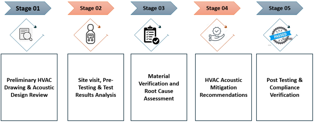
Stage1: Preliminary HVAC Drawing & Acoustic Design Review
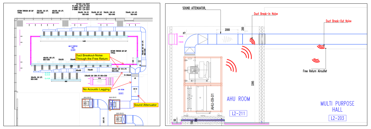
- From the initial drawing review it was identified, they have used 25mm acoustic liner and High performance sound attenuator also as per design recommendation. However, the sound attenuator location was positioned inside the AHU plant room, reducing its effectiveness against downstream break-in noise.
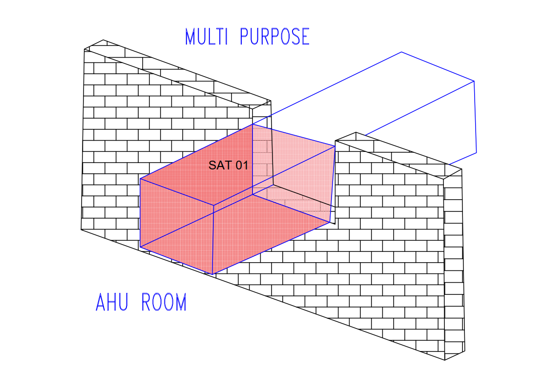
- Multiple AHUs were located inside the adjacent AHU room connected to the multipurpose hall.
- High airflow ducts were routed through the ceiling void above the Multipurpose Hall.
Stage1: Result
The preliminary review helped identify the likely dominant noise paths and optimise the acoustic field testing locations.
Stage2: Site visit, Pre-Testing & Test Results Analysis
Conserve conducted a site visit to confirm readiness for testing and then carried out acoustic measurements using a calibrated sound level meter.
Testing Location & Results:
- Centre of the room, where directly below the supply diffuser 37 NC
- Near to the AHU room wall 44 NC
- Below the Open Return 38 NC
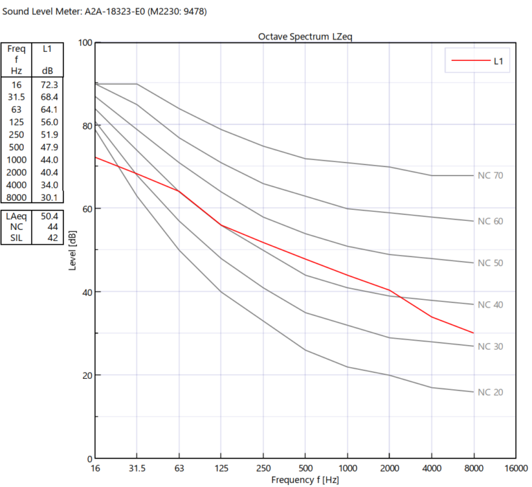
Stage2: Result
Based on measurements and site observations, the primary noise impacts were:
- Noise ingress from the adjacent AHU room
- HVAC duct breakout noise through the ceiling void and open return path
Stage3: Material Verification and Root Cause Assessment
Material verification was performed for selected AHUs, acoustic duct liner, and sound attenuators.
Findings:
- Individual AHU sound levels complied with the project requirements, but combined noise from multiple AHUs operating in a reflective plant room significantly increased overall noise due to reverberation.
- The selected high‑performance sound attenuator met the specified insertion loss and effectively controlled in‑duct equipment noise.
- Acoustic liner requirements were only generally stated in the design. Verification was therefore carried out against ASHRAE Chapter 49 and ASTM C1071, which require a minimum 25 mm thickness, 24 kg/m³ density, and minimum absorption performance corresponding to NRC 0.45. The selected liner (25 mm, 32 kg/m³) provided higher absorption coefficients than the minimum ASTM C1071 requirement and achieved NRC 0.75, confirming compliance.
- High‑airflow ducts above the multipurpose hall ceiling void had no acoustic lagging, leading to:
i) Plant room noise break‑in through the duct system
ii) Duct breakout noise through the free return air path - The common double‑hollow‑block partition wall between the AHU room and the hall provided sufficient sound reduction performance (Rw > 65 dB).
- The receiver room (multipurpose hall) finishing properties also slightly influenced the room noise criteria. . In this project, the ceiling was covered with approximately 60% acoustic ceiling, and the room was furnished with upholstered furniture, provides good sound absorption.
Stage3: Result
- AHUs (individual), acoustic liner, sound attenuator, and the block partition wall were all compliant with acoustic requirements.
- Excessive noise was not due to equipment failure or inadequate material performance.
- Primary root causes were:
- Combined noise from multiple AHUs in a reverberant plant room
- Sub‑optimal sound attenuator placement within the AHU room
- HVAC duct breakout noise above the ceiling void transmitting via the open return path
Stage4: HVAC Acoustic Mitigation Recommendations:
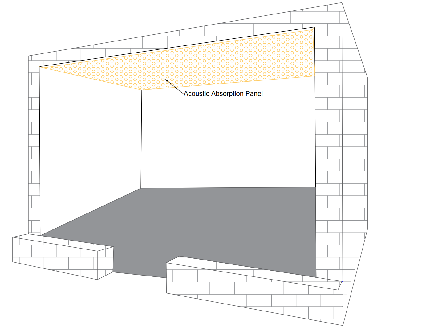
- To control the combined noise level from multiple equipment and reduce echo (reverberation), Class C NRC 0.7 acoustic absorption panels consisting of Rockwool insulation protected with perforated GI sheet were recommended for the entire ceiling arrangement while maintaining Fire & Safety compliance.
- The sound attenuator location was relocated near the plant room terminal / initial receiver room position to reduce AHU room duct break-in noise.
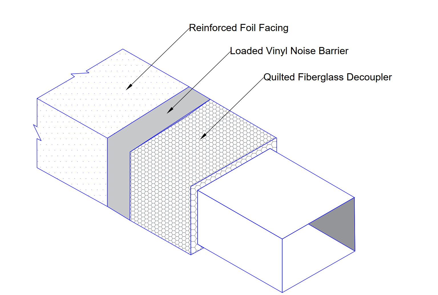
- To reduce duct breakout noise through the open return and plant room noise break-in through the HVAC ducts, acoustic lagging material with a minimum 5 kg/m² surface density reinforced foil-faced loaded vinyl barrier bonded to a 25 mm thick scrim-faced quilted fiberglass absorber was proposed.
Stage 5: Post Testing
After implementation of the mitigation measures, retesting was performed at the same locations.
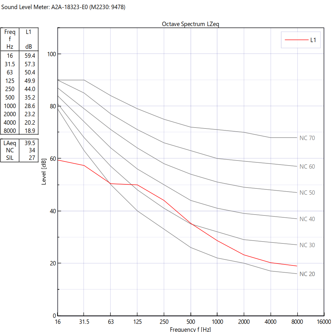
Post treatment NC values:
- Centre of the room (below supply diffuser): NC 34
- Near AHU room wall: NC 28
- Below the open return: NC < 25
Final Outcome
All test locations achieved compliance with the employer’s NC 35 acoustic requirement.
C. Integration (Impact layer)
The proposed HVAC acoustic mitigation measures were integrated into the existing MEP and architectural systems without major redesign or shutdown of ongoing project activities. The recommendations were developed considering practical site constraints, fire & safety compliance, ceiling coordination, HVAC airflow performance, and future maintainability.
The mitigation strategy also established a scalable acoustic control approach that could be directly replicated across future towers and multipurpose halls using the same HVAC design philosophy.
Before vs After
Testing Location | NC Requirement | Pretesting, NC | Post Testing, NC |
Centre of the room, where directly below the supply diffuser | 35 | 36 | 34 |
Near to the AHU room wall | 44 | 28 | |
Below the Open Return | 38 | <25 |
Project Timeline
Total duration: 7 Working days
- Day 1: Drawing review and preliminary HVAC acoustic analysis
- Day 2 & 3: Site inspection and acoustic field testing
- Day 4 & 5: Material verification, root cause analysis, mitigation proposal.
(After material procurement & Installation)
- Day 6 & 7: Final testing and compliance verification
Delivered - What We Delivered
- Detailed HVAC acoustic root cause analysis and noise‑path mapping
- Material verification against 2023 ASHRAE Chapter 49 and ASTM C1071
- Practical mitigation design (plant‑room absorption, optimised attenuator placement, duct lagging)
- Post‑implementation testing report demonstrating NC‑35 compliance in the multipurpose hall
Software and Technology Used
- Calibrated sound level meter
- NTI Room Acoustics Reporter
- Analytical calculations as per 2023 ASHRAE Handbook, Chapter 49, and ASTM C1071
Why Conserve Solutions
Conserve Solutions stands out because we go beyond standard acoustic material checks. Our approach combines site investigation, technical reasoning, HVAC noise path analysis, and practical implementation.
We do not only identify noise problems; we help clients solve them in a way that is:
- Source Path Receiver analysis
- Real-world HVAC noise transmission behaviour
- Fast-track troubleshooting
- Scalable acoustic solutions for future developments
Client Outcome
Conserve Solutions successfully identified the actual root causes of the excessive HVAC noise within a very short project timeline. Through detailed acoustic investigation, HVAC noise path analysis, and targeted mitigation measures, the multipurpose hall achieved full compliance with the employer’s NC 35 acoustic requirement.
The implemented solution effectively reduced AHU room reverberation and duct breakout noise without major redesign or costly modifications. The approach also provided a scalable solution framework that could be replicated across future towers and multipurpose halls.
The project improved client confidence, minimized the risk of repeated acoustic non-compliance, and supported timely project completion.
Author

Prabakaran B
An emerging Architectural & Environmental Acoustics Engineer in the AEC industry with nearly 4 years of experience in acoustic consultancy, environmental noise modelling, building acoustics, and HVAC noise control. Prabakaran specializes in delivering acoustic engineering solutions for hospitality, commercial, residential, educational, and industrial developments. He is experienced in advanced acoustic simulation and analysis using CadnaA, EASE, and INSUL software for environmental noise assessment, sound insulation studies, and building acoustic performance evaluations. Currently working as an Executive Engineer, he supports project execution, technical reporting, client coordination, acoustic data analysis, and mentoring junior engineers. He actively contributes to acoustic compliance strategies, sustainable building performance, and technical excellence through innovative and practical acoustic engineering solutions.

Quick Links
Copyrights © 2026. Conserve Solutions. All Rights Reserved.
BIM Data, Cost & Handover Services
BIM Coordination & Constructability
BIM Modelling & Digital Delivery
Discipline BIM Modeling (Architectural, Structural, MEP)
BIM Automation & Digital Engineering
BIM Data, Cost & Handover Services
Structural & Steel Detailing Services
Architectural Design, Visualization & Presentation Support
BIM Coordination & Constructability
BIM Modelling & Digital Delivery