- Inspire
- Innovate
- Integrate

- Home
- Case Studies
- CFD Investigation of Airflow Recirculation Between Diesel Generators and Chillers in a Data Center Facility Under Extreme Ambient Conditions
CFD Investigation of Airflow Recirculation Between Diesel Generators and Chillers in a Data Center Facility Under Extreme Ambient Conditions
Project Snapshot
| Parameter | Details |
|---|---|
| Client | Data Center Facility in Middle East |
| Sector | Data Centre |
| Platform / Software | Ansys CFX |
| Key Outcomes | • Ensured proper airflow under worst-case conditions (50°C, NW wind) • Confirmed no hot air recirculation into generator or chiller intakes • Identified recirculation issues and suggested design improvements where required |
Problem Statement
We want to ensure that under worst-case conditions, hot air from the generators is not drawn back into their air intakes, and that hot air from both the generators and the chillers is not recirculated or re-entering the system. This is to ensure performance is not affected and that the system can operate at full load without any loss in cooling capacity while meeting peak data centre demand.
Impact of Challenges
- Cooling efficiency loss:
If hot exhaust air from generators or chillers is drawn back into nearby air intakes, the incoming air temperature increases. This reduces cooling effectiveness and overall data centre performance. - Generator performance risk: Hot exhaust air being drawn back into the generator air intake can increase intake temperatures, leading to reduced efficiency, potential derating, and unreliable operation under peak load conditions.
- Reduced peak performance:
At high ambient temperatures, cooling systems operate near limits. Recirculated heat may force capacity reduction to protect IT loads, limiting output. - Higher energy use:
As intake temperatures rise, cooling systems work harder, increasing power and fuel consumption and reducing overall efficiency.
Conserve Solutions - How We Solved It
a. Thinking (Strategy)
We understand that the client’s concern was not the high ambient temperature, as this was already considered in the design. The main concern was whether hot air released from the generators on the ground, or from the chillers on the rooftop, could be blown back into the same equipment under real wind conditions. To check this, an external CFD study was carried out using a detailed 3D model of the actual site, real equipment data, and worst-case weather conditions. The purpose was to confirm that the design will work properly even in extreme conditions, meet full data centre demand, and ensure that hot air from the generators and chillers is safely carried away without being drawn back into the system.
b. Execution (What We Built)
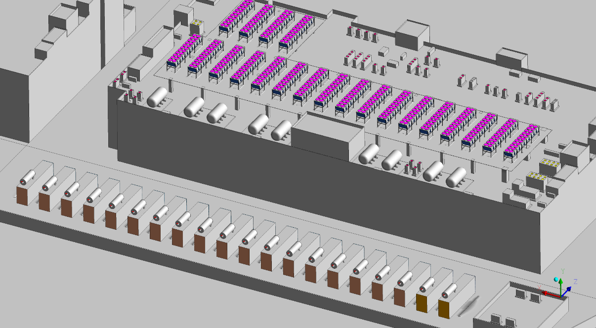
- Modelled and reconstructed the full 3D building geometry from BIM files
- Represented all rooftop chillers with accurate airflow inlet and outlet zones and thermal separation.
- Represented all generator units with correct intake, exhaust, and flue discharge locations.
- Applied worst-case design conditions in line with ASHRAE: 50°C ambient temperature, northwest wind, and suburban wind profile.
- Developed a detailed 3D computational mesh to accurately capture airflow behaviour around the site.
- Performed advanced airflow and heat transfer simulation using standard turbulence and buoyancy modelling techniques with high-accuracy numerical schemes.
c. Integration (Impact Layer)
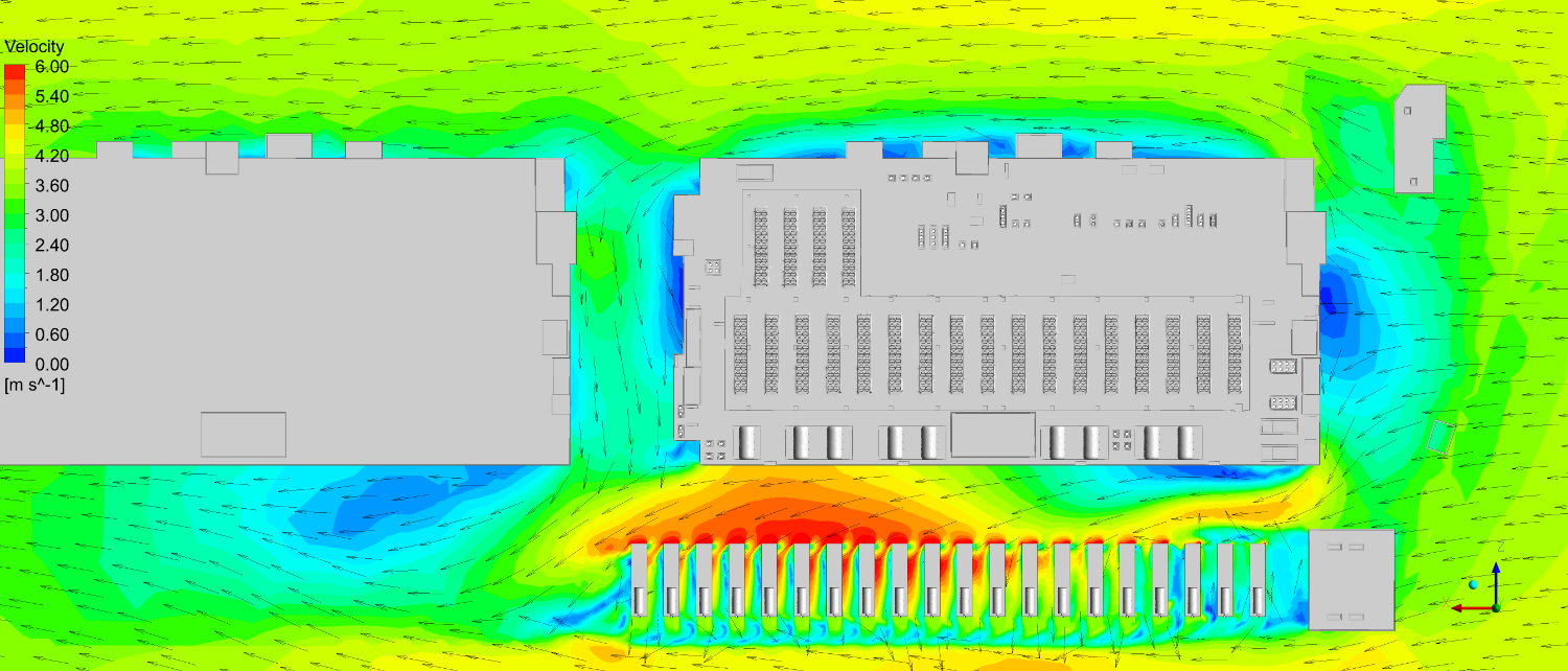
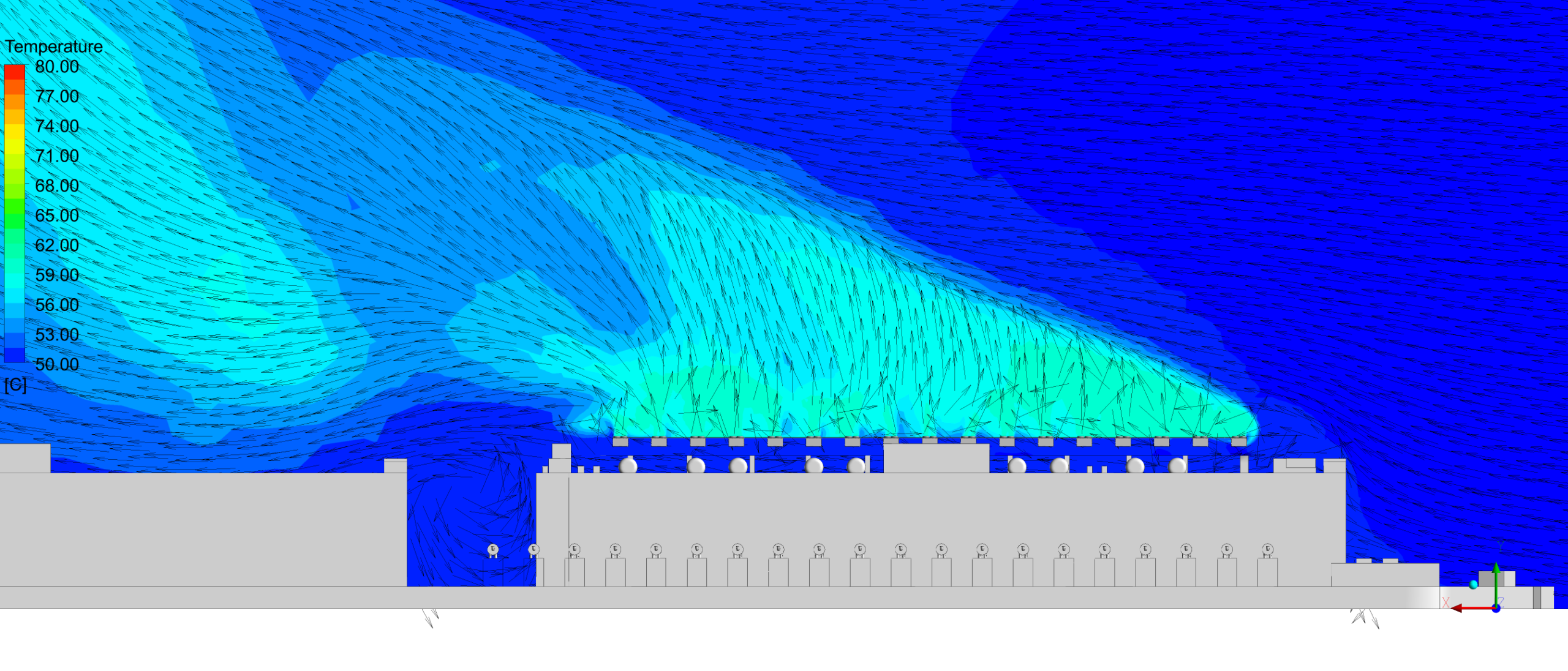
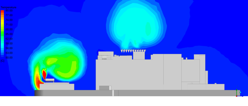
- Presented simulation results using temperature and velocity contour plots across key sections, including chiller inlets/outlets, generator intakes/exhausts, and building mid-level planes.
- Performed detailed statistical analysis for each individual chiller to assess thermal performance.
- Enabled identification of specific airflow and temperature variations across equipment.
- Supported development of targeted and location-specific design recommendations.
Project Timeline:
Phase 1 – Day 1-4 | Kick-off, data collection, boundary condition setup, and CFD-compatible 3D model development |
Phase 2 – Day 5-8 | Mesh independence study and CFD simulations. |
Phase 3 – Day 9-12 | Post-processing, ASHRAE validation, and final report submission |
Delivered – What we delivered:
- Full 3D CFD model of the Data center building geometry including all the rooftop chiller compound and ground-level generator plant
- Temperature and velocity contour maps across result planes (chiller, generator, exhaust, and building mid-surfaces)
- Per-chiller inlet temperature statistics identifying all derating exceedances
- Root cause analysis of recirculation (wind-forced downdraught between upstream fan outlets)
- Actionable design recommendation: barrier containment panel placement between chillers to prevent downdraught recirculation
- Full CFD Analysis Report with methodology, assumptions, limitations, and design guidance
Software and Technology Used:
- Ansys CFX
Before vs After Automation (High Impact Section)
Metric | Before (Design Assumption) | After (CFD Validated) |
Thermal Visibility | Limited to general assumptions with no clear insight into how air and heat behave across the external plant. | Complete 3D visibility of airflow patterns and temperature distribution across the entire data centre compound. |
Hotspot Identification | Recirculation risks and thermal hotspots were assumed but not identified or confirmed. | Precise identification of recirculation zones, hotspots, and temperature variations across all chillers and generators. |
Cooling Efficiency | Airflow separation assumed adequate; no validation of performance under real wind and temperature conditions. | Cooling performance validated under worst-case conditions; recirculation resolved through targeted barrier containment. |
Why Conserve Solutions
- Managed the full project lifecycle from setup to final delivery, ensuring coordination, accountability, and alignment with project goals and timelines.
- Applied strong engineering principles to ensure the study reflected real-world conditions and actual system behaviour.
- Developed and ran simulations for both normal and worst-case scenarios to assess performance under critical conditions.
- Presented results in a clear and structured way, making them easy to understand for both technical and non-technical stakeholders.
- Delivered actionable insights to support decision-making, system verification, and confidence in overall design performance.

Client Outcome
The client was confident that the systems would operate as intended under real conditions. The study provided early insights into potential issues, allowing them to be resolved without impacting schedule or cost.

Quick Links
Copyrights © 2026. Conserve Solutions. All Rights Reserved.
BIM Data, Cost & Handover Services
BIM Coordination & Constructability
BIM Modelling & Digital Delivery
Discipline BIM Modeling (Architectural, Structural, MEP)
BIM Automation & Digital Engineering
BIM Data, Cost & Handover Services
Structural & Steel Detailing Services
Architectural Design, Visualization & Presentation Support
BIM Coordination & Constructability
BIM Modelling & Digital Delivery