Wet wells are underground or partially submerged structures that receive wastewater flows from gravity sewer lines. Their primary purpose is to store wastewater temporarily until it reaches a predetermined level, at which point pumps are activated to lift the wastewater to higher elevations or treatment facilities. Wet wells vary in size and shape depending on the system’s requirements and hydraulic conditions, and their proper design is crucial to prevent issues such as pump cavitation, debris accumulation, and odor generation.
The design and operation of wet wells in wastewater systems play a crucial role in maintaining the efficiency and safety of the overall infrastructure. Wet wells are key components of pump stations that collect and temporarily store wastewater before it is pumped to higher elevations for further treatment. Computational fluid dynamics (CFD) simulation is a powerful tool to optimize wet well designs, ensuring optimal performance, mitigating potential issues, and reducing operational costs. This article explores the below,
Problem Statement.
Preparation of 3D Model and Meshing in commercial CFD Software.
Defining the Boundary Conditions and parameters.
Carry out the CFD Simulation.
Analyze the results and provide suitable engineering recommendations to overcome the Non-Conformances.
1. Problem Statement:
To understand the flow pattern inside the pump impeller and verify whether the noted swirl angle is within the allowable limit as per ANSI / HIS Standards.
To understand the sedimentation transportation of the suspended particles inside the wastewater and its stagnation point inside the Wet Well.
To verify the proposed location and inclination of the mixer inside the Wet Well is suitable to eradicate the sedimentation process.
To understand the flow velocity and wall shear of the wastewater across the entire boundary.
2. Preparation of 3D Model and Meshing in commercial CFD Software:
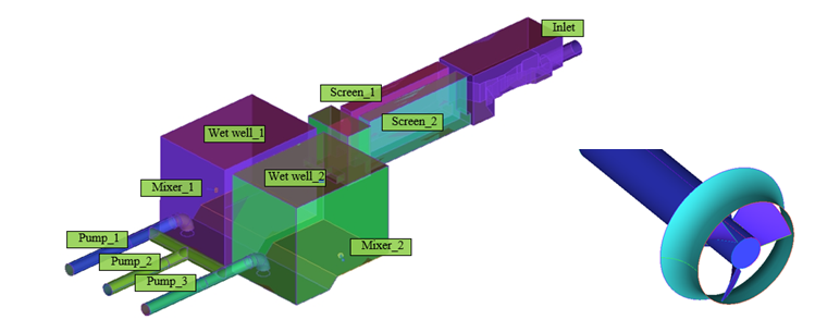
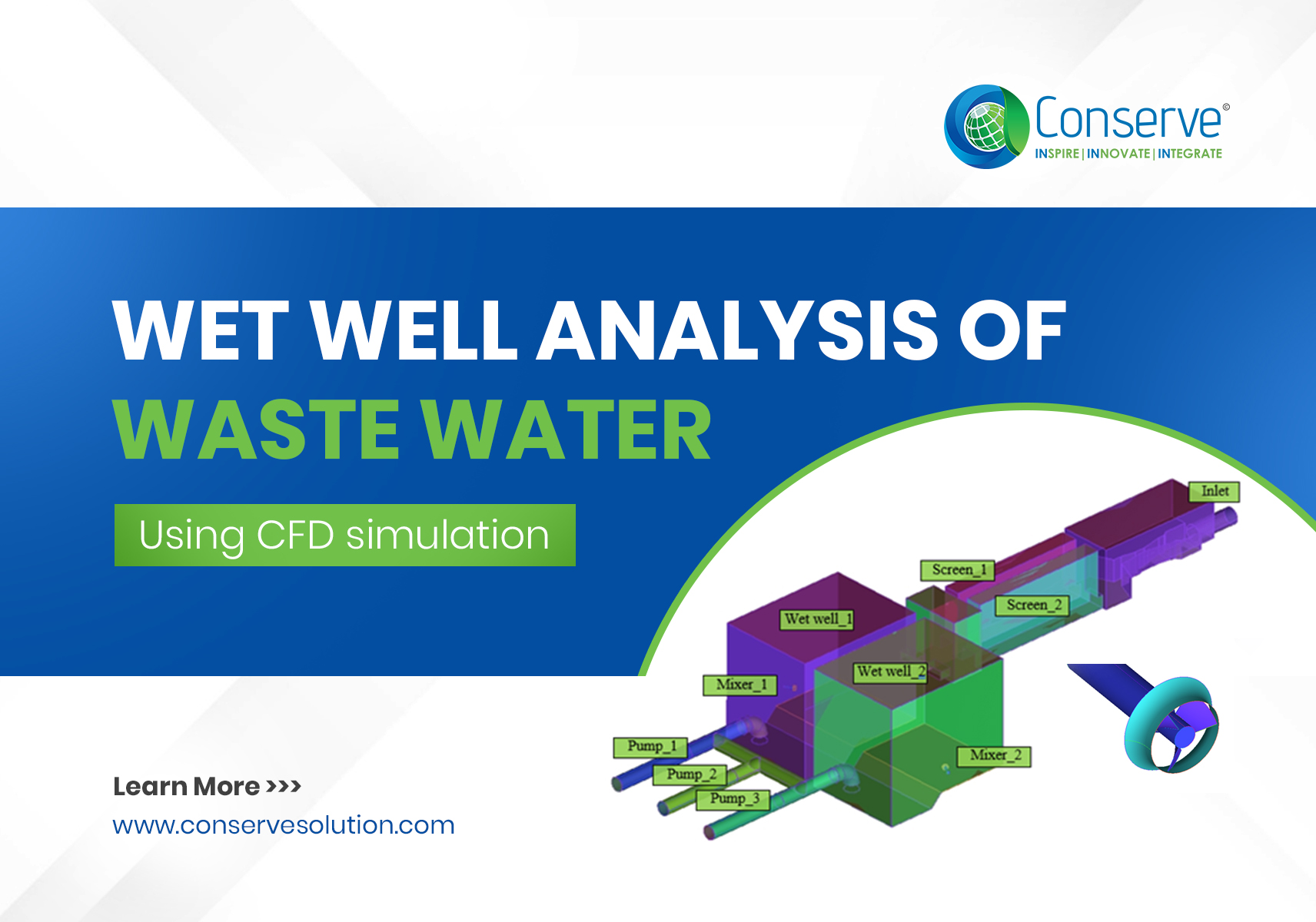
The 3D Model and Meshing of the entire Wet Well has been carried out in Commercial CFD Software by CFD Experts of Conserve and including the proposed mixer to be placed inside the Wet Well. The below snapshots highlight the aesthetic of the prepared 3D Model.
3. Defining the Boundary Conditions and parameters:
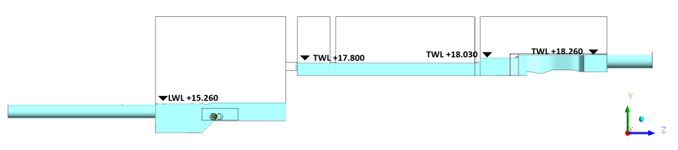
The Boundary Conditions for the above domain have been fixed based on the minimum and maximum flow rate provided by the Client along with the level of Wastewater inside the entire domain from the Inlet Lift Station up to the Pump suction. The below snapshot highlights one such condition where the levels of the Wastewater have been fixed based on the project requirements.
4. Carry out the CFD Simulation:
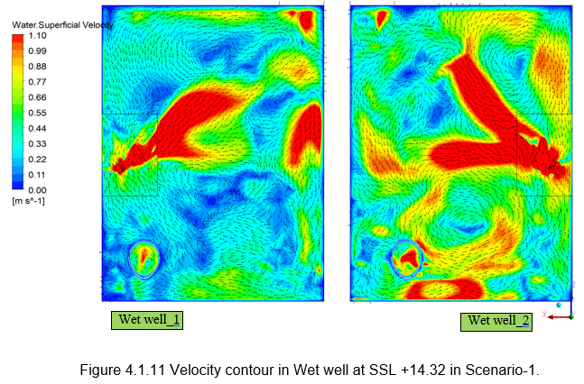
Based on the problem statement Conserve has carried out transient analysis of the entire domain and obtained the CFD results for the items listed in Section 1 Problem Statement. The contour plots have been plotted against different levels based on the project requirements and the sample snapshots of the obtained output are shown below,
• Velocity Contour inside the Wet Well:
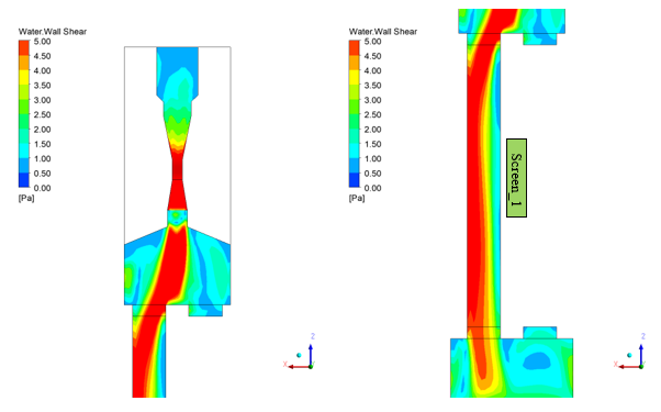
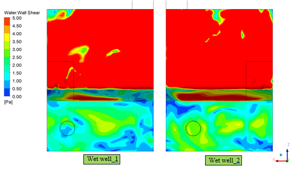
• Wall Shear Contour across the entire domain:
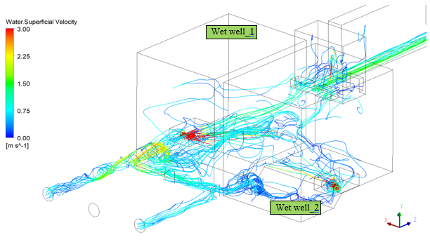
• Flow Stream Contour across the Wet Well:
5. Result outcomes and Engineering Recommendations:
Based on the above results the wall shear and swirl angle at certain conditions exceeded the standard allowable limits and project specifications. Conserve with its expertise engineering capabilities proposed modification on the blades of the provided mixer and recommended a flow control device at the pump suction of the Wet Well to overcome the Non-conformance.
With over 6+ years of experience within the Built Environment, I specialize in project management and team leadership, successfully overseeing the execution of 35+ diverse projects across commercial, healthcare, retail, high-rise towers, infrastructure, and hospitality sectors. My expertise lies in conducting and handling CFD analysis, Piping Analysis, Structural Analysis, HVAC calculations, and utilizing 3D laser scanning and BIM methodologies within the realm of building services and Oil & Gas.