- Inspire
- Innovate
- Integrate
- Home
- Case Studies
- CFD Thermal Validation Eliminates Hotspot Risk and Confirms N+2 Cooling Redundancy for Abu Dhabi Data Centre
CFD Thermal Validation Eliminates Hotspot Risk and Confirms N+2 Cooling Redundancy for Abu Dhabi Data Centre
Project Snapshot
Parameter | Detail |
Client | Data centre facility |
Sector | Data Centre |
Location | Abu Dhabi |
Platform / Software | Ansys CFX |
Standards | ASHRAE TC 9.9 |
Service | Conserve Solutions – Simulation & Analysis Division |
Key Outcome | Cooling design validated pre-construction; ASHRAE TC 9.9 compliance confirmed; |
Problem Statement
We were designing a critical data centre facility and needed confidence in our cooling strategy before committing to the final layout. Our proposed design assumed N+2 redundancy and a hot-aisle/cold-aisle containment approach, but we had no way to verify thermal performance or identify airflow risks without simulation. We needed CFD to de-risk the design before construction.
Impact of Challenges
- Design Risk: Committing to a cooling layout without thermal simulation risked costly redesign or post-construction retrofitting
- Compliance Exposure: Without CFD-backed evidence during design, the facility risked ASHRAE TC 9.9 non-compliance at the commissioning stage
- Redundancy Confidence: N+2 cooling redundancy was assumed in the design – not proven. Any single failure scenario was unquantified prior to construction sign-off.
- Design Blind Spots: Recirculation paths and airflow imbalances cannot be detected through manual design review – CFD was the only reliable method to resolve this before build.
Conserve Solutions - How We Solved It
a. Thinking (Strategy)
Conserve approached this as a design de-risking exercise, not a routine simulation task. The client needed thermal evidence to finalise their cooling layout with confidence – before any commitment to construction. We structured the analysis around two critical design scenarios: normal full-capacity operation and the N+2 worst-case cooling failure. This gave the design team actionable data across both every day and contingency conditions.
b. Execution (What We Built)
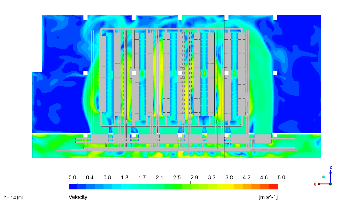
- Developed a high-fidelity 3D CFD model of the data centre in Ansys CFX, incorporating server rack layout, FWU unit positioning, raised-floor plenum, and tile perforation patterns
- Simulated two operating scenarios: (1) full cooling capacity – normal operation, and (2) N+2 redundancy scenario – worst-case cooling unit failure
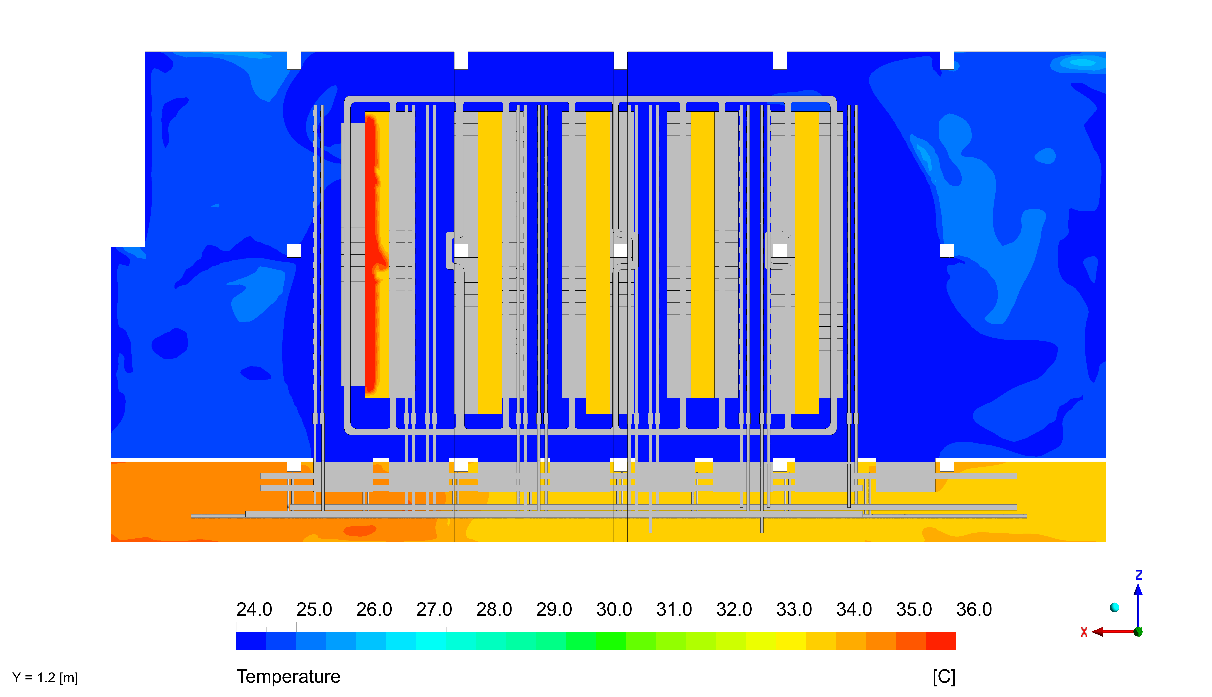
- Mapped cabinet inlet temperatures across all server racks against ASHRAE TC 9.9 thermal envelopes
- Quantified recirculation zones and hot-aisle/cold-aisle crossover risks
- Validated cooling unit external static pressure (ESP) against manufacturer performance curves under both scenarios.
c. Integration (Impact Layer)
CFD outputs were directly mapped to ASHRAE TC 9.9 design thresholds and integrated into the client’s design review process. The team received visual contour maps, airflow velocity plots, and a structured recommendation matrix – enabling informed decisions on rack placement, tile perforation ratios, and FWU unit sizing before finalising the design.
Project Timeline:
Phase 1 : Day 1 – 3 | Kick-off, data collection, boundary condition setup, and 3D model development |
Phase 2 : Day 4 – 7 | Mesh independence study and CFD simulations both normal operation and N+1 failure scenarios. |
Phase 3 : Day 8 – 12 | Post-processing, ASHRAE validation, and final report submission |
Delivered:
- Full 3D CFD model (Ansys CFX) – normal and N+2 redundancy scenarios
- Temperature contour maps – all cabinet rows, floor and rack level
- Velocity vector plots – airflow distribution and recirculation visualisation
- ASHRAE TC 9.9 compliance summary – cabinet inlet temperature validation
- ESP performance validation report – cooling unit operating point confirmation
- Risk mitigation recommendations – recirculation and hotspot resolution guidance
- Client-ready technical report with executive summary
Software Used:
Ansys CFX | Primary CFD solver – thermal and fluid flow analysis |
ASHRAE TC 9.9 | Thermal compliance standard for data centre equipment |
Manufacturer ESP Curves | Cooling unit performance validation reference |
Before vs After (Measurable Difference)
Metric | Before (Risk) | After CFD Validation | Improvement |
Cabinet Inlet Temperature | Unknown – hotspots could exist undetected | All cabinets within 18–27°C ASHRAE range | ASHRAE Compliant |
Cooling Unit Performance (ESP) | Unvalidated against real operating conditions | Confirmed within manufacturer limits for both scenarios | Within spec |
N+2 Redundancy Confidence | Assumed – not proven | Worst-case scenario simulated and confirmed safe | Risk eliminated |
Hotspot / Recirculation Risk | High – undetected recirculation possible | Identified, quantified and mitigated by design | Risk minimised |
Why Conserve Solutions
Design-phase thinking – we modelled what matters before construction, not after
Standards-driven delivery – every output benchmarked directly against ASHRAE TC 9.9 design thresholds
Dual-scenario methodology – normal operation and worst-case N+2 failure both covered in a single engagement
Vendor-neutral validation – ESP performance confirmed against manufacturer curves, not design assumptions
Scalable approach – methodology directly reusable for future expansion phases or additional facilities
Client Outcome
Conserve’s CFD analysis gave us the confidence to finalise our cooling design without second-guessing. Having the N+2 scenario simulated and cleared before construction meant we could commit to the layout knowing the design had been stress-tested. It removed the biggest technical uncertainty from our project
– Development Manager, Manchester Mixed | Use Project
Quick Links
Copyrights © 2026. Conserve Solutions. All Rights Reserved.
BIM Data, Cost & Handover Services
BIM Coordination & Constructability
BIM Modelling & Digital Delivery
Discipline BIM Modeling (Architectural, Structural, MEP)
BIM Automation & Digital Engineering
BIM Data, Cost & Handover Services
Structural & Steel Detailing Services
Architectural Design, Visualization & Presentation Support
BIM Coordination & Constructability
BIM Modelling & Digital Delivery