- Inspire
- Innovate
- Integrate
- Home
- Case Studies
- CFD-driven thermal analysis of hybrid-cooled data centres to validate its cooling performance and efficiency and ensure ASHRAE compliance
CFD-driven thermal analysis of hybrid-cooled data centres to validate its cooling performance and efficiency and ensure ASHRAE compliance
Project Snapshot
| Category | Details |
|---|---|
| Client | Data Center Facility in Qatar |
| Sector | Data Centre |
| Platform / Software | ANSYS CFX |
| Standards | ASHRAE TC 9.9 (A1 & A2 Compliance) |
| Key Outcomes | • Cooling performance verified under normal and failure conditions• Equipment temperatures remained within safe limits • No overheating or hot spots observed • Airflow distribution was efficient and balanced |
Problem Statement
The client’s data centre facility in Qatar, featuring a raised floor cooling system with hot aisle containment, is being upgraded from an air-cooled configuration to a hybrid cooling system to support high-density racks. As part of this transition, there is a need to evaluate the thermal performance of the data hall and assess the reliability of the cooling infrastructure. A CFD-based thermal simulation is required to verify that the upgraded system can maintain safe operating temperatures under both normal conditions and potential cooling unit failure scenarios, ensuring reliable and efficient operation prior to commissioning.
Impact of Challenges
- Overheating Risk – Poor cooling performance may lead to high rack inlet temperatures, which can reduce equipment reliability and potentially cause hardware failure.
- Leakage Impact – Leakage from hot or cold aisle containment can disrupt designed airflow patterns, leading to uneven cooling across racks.
- ESP Impact – Excess external static pressure in the airflow path can reduce delivered air volume from cooling units, impacting overall system effectiveness.
- Compliance Risk – If temperature limits are not maintained, the facility may not meet required guidelines such as ASHRAE standards during commissioning.
- Cost & Delay Risk – Identifying and correcting cooling issues after installation would require significant rework, increasing both cost and project delays.
Conserve Solutions - How We Solved It
a. Thinking (Strategy)
We evaluated the system under worst-case conditions, including both normal operating conditions and critical failure scenarios, to ensure it remains safe, reliable, and stable even under the most demanding situations. This approach provides a complete understanding of system performance beyond standard operation. The results were then presented in a clear and practical way, making it easy to interpret key findings and directly support informed engineering and commissioning decisions.
b. Execution (What We Built)
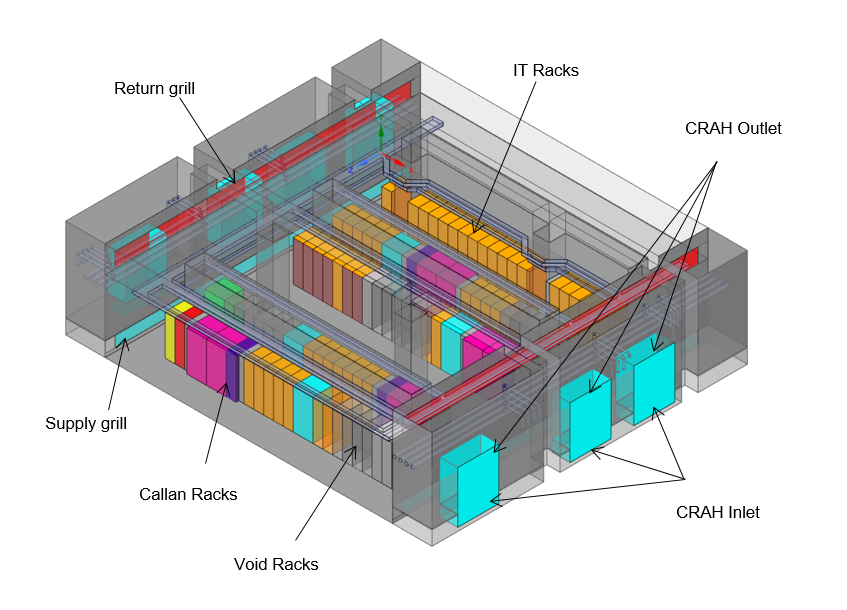
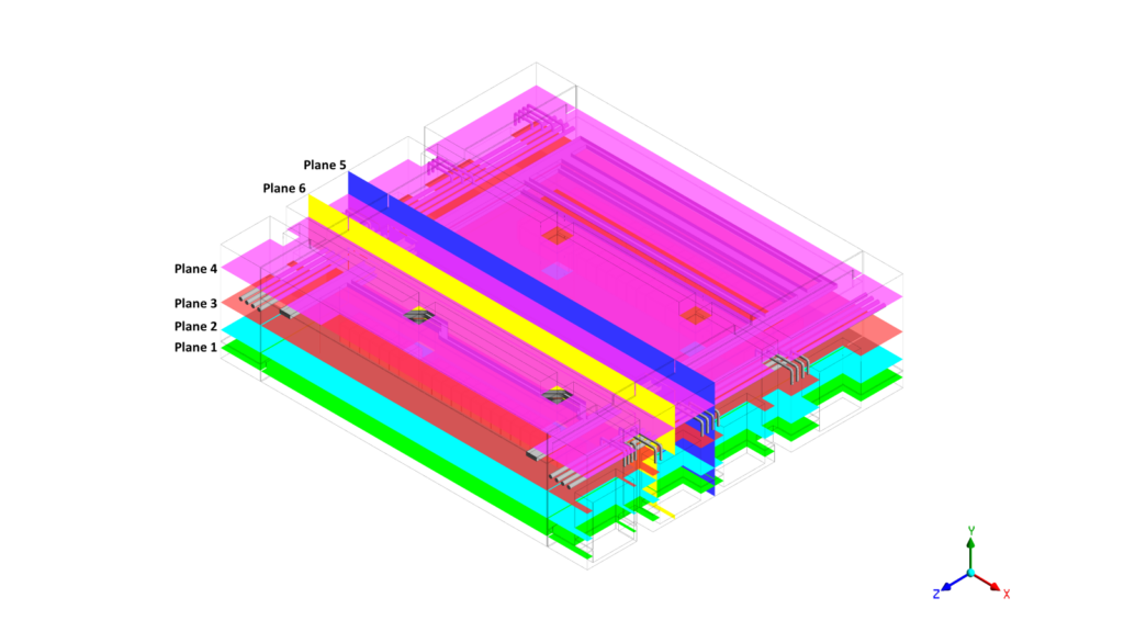
- Developed a digital model of the full data centre including racks and cooling units
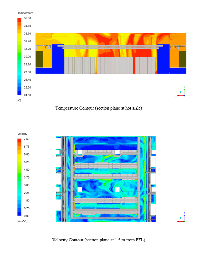
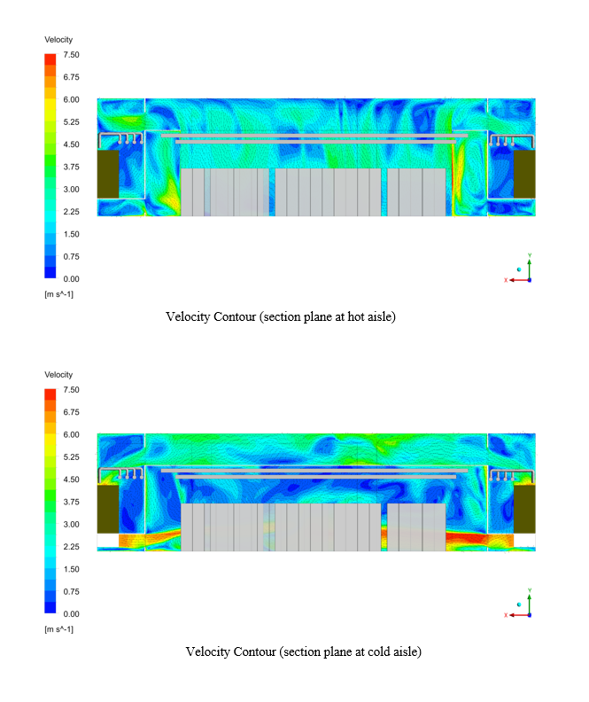
- Simulated airflow and temperature distribution across the space
- Included total heat load from all equipment
- Considered small air leakages and real operating conditions
- Tested both normal operation and backup (failure) scenarios
c. Integration (Impact Layer)
- Compared results with actual temperature sensor locations
- Provided clear temperature distribution across all racks
- Enabled easy comparison with real-time monitoring systems
Project Timeline:
Completed within the agreed project schedule (2 weeks)
Phase 1 : Day 1 – 3 | Kick-off, data collection, boundary condition setup, and 3D model development |
Phase 2 : Day 4 – 7 | Mesh independence study and CFD simulations both normal operation and N+1 failure scenarios. |
Phase 3 : Day 8 – 12 | Post-processing, ASHRAE validation, and final report submission |
Delivered – What we delivered:
- Full 3D CFD model of the data hall, including all rack types, CRAH units, and containment geometry
- Temperature, velocity, and pressure contour plots for all scenarios as per requirements
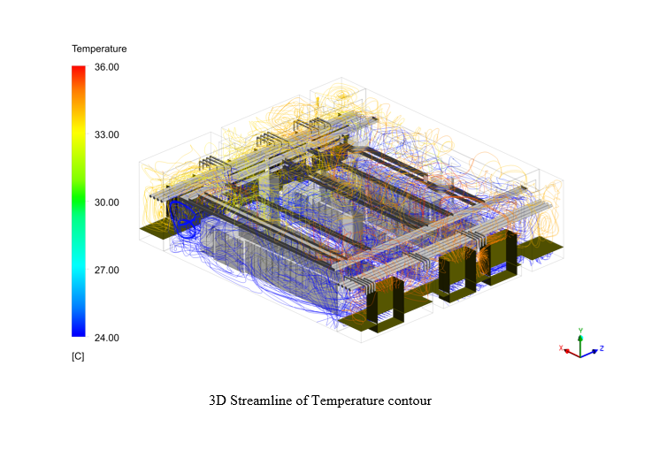
- 3D streamline visualisations with temperature mapping for all scenarios
- Confirmation of compliance with industry standards
- Clear conclusion on system performance and reliability
- Guidance on system limitations and design considerations
Before vs After Automation (High Impact Section)
Metric | Before (Design Assumption) | After (CFD Validated) |
Thermal Visibility | Based on general assumptions with limited insight into airflow, temperature, and pressure distribution. | Full 3D visualization of airflow, temperature, and pressure across the data hall. |
Hotspot Identification | Not clearly identified; risks assumed from layout and load distribution. | Accurate identification of hotspots, recirculation zones, and thermal variations. |
Failure Preparedness | Not validated, leading to uncertainty in system reliability. | Performance validated across operating conditions, ensuring confidence in cooling. |
Cooling Efficiency | Assumed uniform airflow, risking over/undercooling. | Optimized airflow with reduced recirculation and improved cold aisle delivery. |
ESP Management | Pressure losses not quantified, impacting airflow delivery. | Pressure distribution analyzed; high-resistance zones identified and optimized. |
Air Leakage & Bypass Flow | Leakage and bypass airflow not considered. | Leakage (~2%) and bypass paths modeled, improving containment performance. |
Why Conserve Solutions?
- Managed the entire project lifecycle, ensuring consistency and accountability.
- Applied strong engineering principles aligned with real-world operation.
- Simulations reflected realistic and worst-case scenarios.
- Delivered easy-to-understand results for both technical and non-technical stakeholders.
- Results supported direct decision-making for operations and system validation.
Client Outcome
The CFD results showed that rack inlet temperatures remain within acceptable limits, even during failure scenarios like CRAH unit outages. It also highlighted a few localized airflow issues that weren’t obvious in the design stage, which we were able to correct early without impacting the schedule. Addressing these upfront helped us avoid costly rework and gave us practical confidence that the cooling system will perform as expected under real operating conditions once the facility goes live.
Quick Links
Copyrights © 2026. Conserve Solutions. All Rights Reserved.
BIM Data, Cost & Handover Services
BIM Coordination & Constructability
BIM Modelling & Digital Delivery
Discipline BIM Modeling (Architectural, Structural, MEP)
BIM Automation & Digital Engineering
BIM Data, Cost & Handover Services
Structural & Steel Detailing Services
Architectural Design, Visualization & Presentation Support
BIM Coordination & Constructability
BIM Modelling & Digital Delivery