- Inspire
- Innovate
- Integrate
- Home
- Case Studies
- Thermal Resilience in Electrical Rooms – Maintaining Cooling During Equipment Outages
Thermal Resilience in Electrical Rooms – Maintaining Cooling During Equipment Outages
Project Snapshot
| Category | Details |
|---|---|
| Client | Data Center Facility in Abu Dhabi |
| Sector | Low Voltage Room |
| Platform / Software | ANSYS CFX |
| Standards | ASHRAE TC 9.9 |
| Key Outcomes | Cooling performance validated against equipment temperature limits; uniform airflow distribution achieved to eliminate hotspots; CRAH unit operation confirmed within the designed pressure range. |
Problem Statement
We were supporting the design of a critical electrical room containing high-density panels and switchgear, where effective cooling is essential to prevent overheating and operational risk. While the design incorporated CRAH-based cooling, there were concerns about how the system would perform under failure conditions. In particular, we needed to understand whether the remaining units could maintain stable temperatures and avoid localized hotspots. To gain this confidence, we applied CFD simulation to evaluate airflow behaviour, test failure scenarios, and optimize the design before construction.
Impact of Challenges
- Scalability limitations:
The system may not easily support future increases in IT load or rack density. - Space constraints:
Limited room for equipment and airflow pathways can restrict optimal system performance. - Failure propagation risk:
A single cooling unit failure can disrupt airflow distribution, causing adjacent zones to overheat. - Bypass airflow losses:
A significant portion of cold air may never reach equipment (escaping through gaps, cable cutouts, or unsealed floors), reducing effective cooling capacity. - Pressure imbalance in the room:
Incorrect air pressure (positive/negative) can disrupt intended airflow direction, pulling in hot air from unintended areas.
Conserve Solutions - How We Solved It
a. Thinking (Strategy)
Conserve approached the LV room CFD with an operational realism mindset, focusing on how the space would actually behave under sustained electrical load and imperfect airflow. The study captured temperature rise patterns often missed in static checks. This ensured the design reflects real-world performance, not assumptions.
b. Execution (What We Built)
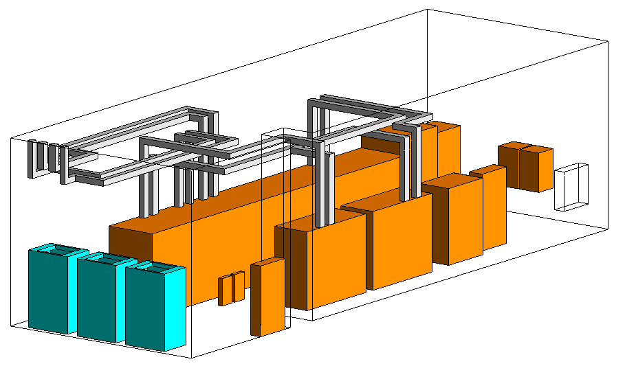
- Developed a high-fidelity 3D CFD model of the LV room in Ansys CFX, capturing detailed geometry including panels, CRAH units, obstructions, and return air paths without simplification
- Applied conservative heat loads across all equipment surfaces to represent continuous full-load electrical operation
- Evaluated two critical operating scenarios: normal operation with all CRAH units active, and an N+1 failure condition with one unit offline to assess system resilience
- Analyzed temperature distribution across all equipment zones, benchmarking results against defined operational limits
- Identified and quantified airflow recirculation zones that could reduce cooling effectiveness
c. Integration (Impact Layer)
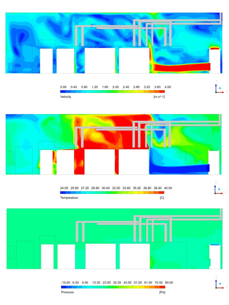
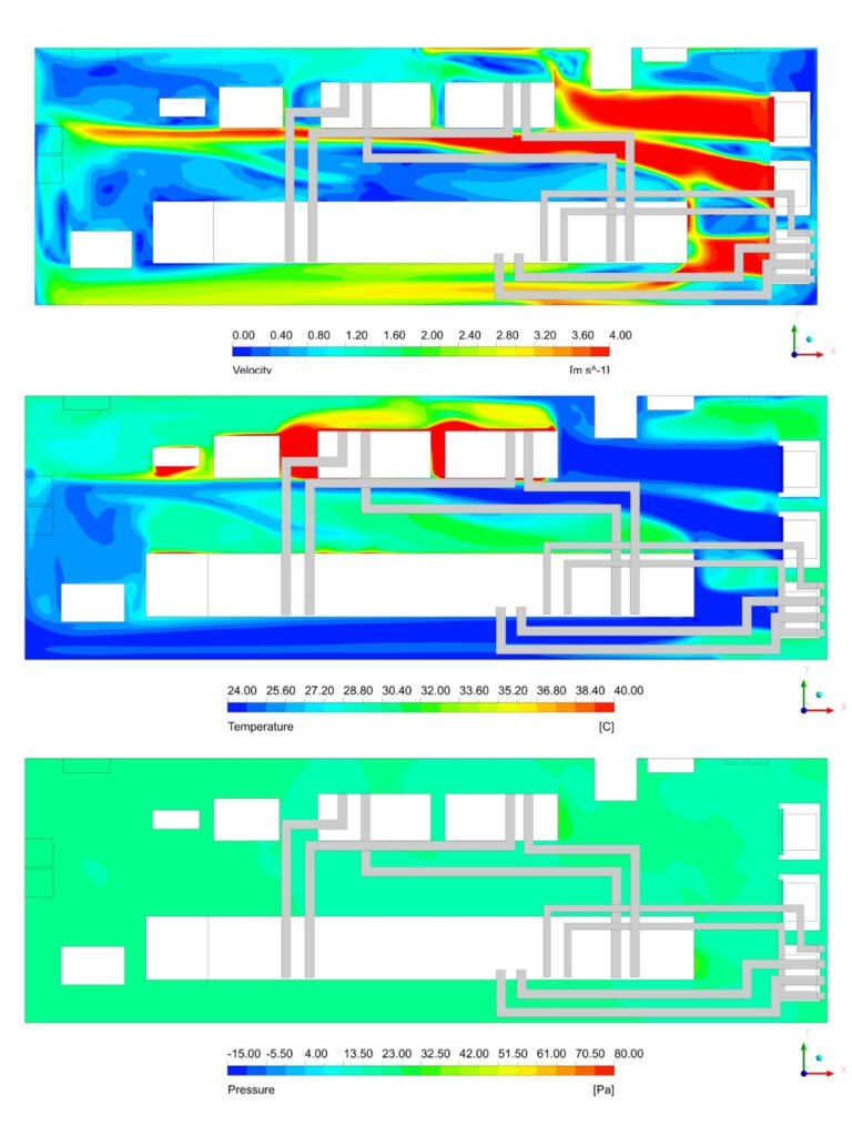
- Delivered CFD results in a structured, coordination-ready format, aligned with the project workflow, including scenario-wise outputs for both normal and failure conditions. Key result planes were provided across critical LV room zones (equipment level, return path, and airflow sections), along with temperature, airflow, and pressure data.
- CRAH performance parameters, including ESP values, were extracted and benchmarked against design requirements, enabling seamless integration with the mechanical design team.
Project Timeline:
Completed within the agreed project schedule (1 weeks)
Phase 1 : Day 1 & 2 | Data collection, geometry modelling, boundary condition setup |
Phase 2 : Day 3 & 4 | CFD simulation runs (normal + N+2 scenarios), mesh refinement |
Phase 3 P: Day 5 & 6 | Post-processing, ASHRAE validation, report preparation and delivery |
Front view & Top view (CRAH Supply)
Delivered - What we delivered:
- Comprehensive CFD-based thermal analysis report of the LV room, covering both normal and failure operation scenarios, confirming no hotspots and safe temperatures across all equipment
- Evaluated cooling unit performance and provided clear visuals of (airflow, temperature, pressure contours) for easy understanding.
- Delivered practical recommendations and final validation, ensuring the system is reliable, compliant, and ready for installation
Before vs After Automation (High Impact Section)
| Metric | Before (Risk) | After Validated | Improvement |
|---|---|---|---|
| Room Temperature | Potential hotspots (uncertain distribution) | Maintained across all equipment | Eliminated hotspots; ensured ASHRAE TC 9.9 compliance |
| CRAH ESP | Not verified / assumed | Confirmed within range | Validated design performance under actual conditions |
| N+1 Redundancy Confidence | Assumed (no failure validation) | Proven through CFD simulation (one unit OFF) | Achieved reliable operation under failure scenario |
Why Conserve Solutions
- Edge case focused analysis – we probe system limits under extreme and off-design conditions, not just steady-state comfort zones
- Granular visibility – insights delivered down to equipment level, not averaged room conditions that hide critical risks
- No black box outputs – every result is explainable, traceable, and defensible in front of stakeholders
Client Outcome
One of the key benefits was the visibility into system behavior under stress. Conserve’s analysis allowed us to identify and address potential airflow and temperature concerns early, before they could impact installation or operation.
Quick Links
Copyrights © 2026. Conserve Solutions. All Rights Reserved.
BIM Data, Cost & Handover Services
BIM Coordination & Constructability
BIM Modelling & Digital Delivery
Discipline BIM Modeling (Architectural, Structural, MEP)
BIM Automation & Digital Engineering
BIM Data, Cost & Handover Services
Structural & Steel Detailing Services
Architectural Design, Visualization & Presentation Support
BIM Coordination & Constructability
BIM Modelling & Digital Delivery