Effectiveness Calculator for Air to Air Heat Recovery System

Conserve have developed web-based tool to calculate the effectiveness of Heat Recovery System as per the standard ASHRAE 84-2013. Effectiveness of Heat Recovery System is an important parameter in GSAS Energy Calculator (also called as GSAS Energia Suite™), in GSAS which is also called as heat recovery efficiency. It is also an input required for Energy Simulation for LEED Credits Minimum and Optimum Energy Performance as per ASHRAE 90.1 (Appendix G)

Access interactive calculation tool from this link: Heat Recovery Effectiveness Calculation

In this article, we have explained the following

  1. Heat Recovery System
  2. Types of Heat Recovery
  3. Heat Recovery Wheel and its working
  4. Performance of Heat Recovery Wheel
  5. Web based tool to calculate the Heat Recovery Performance

1. Heat Recovery System

The working principle of Heat Recovery is based on the first law of thermodynamics: “Energy can neither be created nor destroyed; rather, it transforms from one form to another.” Hence here the heat transfers between the exhaust and Fresh air.
Heat Recovery is a ventilation system which works on the principle of first law of thermodynamics by extracting and supplying air to ensure good indoor air quality.
Heat recovery system is used for pre-conditioning the fresh air by using the energy of the exhaust air (by reducing the enthalpy of fresh air in summer time and increasing the enthalpy in winter time). Pre-conditioned air thus shall require less heating/cooling for the required supplying temperature and therefore, energy recovery shall be achieved.

Following are the benefits of HRS:

  1. Reduction in energy cost
  2. Reduction in the cost of capital equipment
  3. Lower operation cost
  4. Reduction in environmental impacts

2. Types of Heat Recovery

In AHUs, we ideally use the following types of Heat Recovery systems:

  • Heat Recovery Wheel
  • Cross Plate Heat Exchanger
  • Round Around Coil
  • Heat Pipe

In this article, we will be explaining the working mechanism of Heat Recovery Wheel with appropriate details to understand the functioning of the system.

3. Heat Recovery Wheel and its working

Heat Recovery Wheel also called as Enthalpy wheels are very common in dedicated fresh handling units and AHUs.

Heat Recovery Wheel (See Fig.1) performs opposite processes in the cooling season and the heating season. When the outside air is hot, the wheel transfers heat from the incoming air to the exhaust air, thus decreasing the amount of cooling needed by the air handling unit and therefore, energy recovery shall be achieved.

Heat recovery systems will reduce the amount of energy consumed by conventional heating/cooling unit by recovering the residue heat from the exhaust air which is used to alter the temperature of the supply fresh air. This is done mostly by drawing heat from predominant heat generating areas like a busy kitchen or wet rooms where the temperature is likely to be higher than other rooms, consequently this helps the system to reduce the burden on the conventional energy.

Let us briefly discuss about the working methodology of Heat Recovery Wheel in hot climatic condition like Qatar.

Fig.2 Heat Recovery Wheel

The climatic condition of Qatar is subtropical dry, hot desert climate with low annual rainfall, very high temperatures ranging from (35 °C – 46 °C) in summer and a big difference between minimum and maximum temperatures (min 12 °C   – max 46 °C).

Having said that, Qatar falls under the hot climatic zone defined by ASHRAE 169-2013 (Climatic Data for Building Design Standards), accordingly ASHRAE has updated the Standard of ASHRAE 169-2013 to change Zone 0 from Zone 1 due to its extreme weather conditions where the maximum ambient temperature can reach easily to 46 °C. In this climatic condition, the conventional HVAC design will increase the energy consumption and capital cost of fresh air handling units and AHUs. In such scenario the heat recovery wheel will help in reducing the hike in energy and cost consumption.

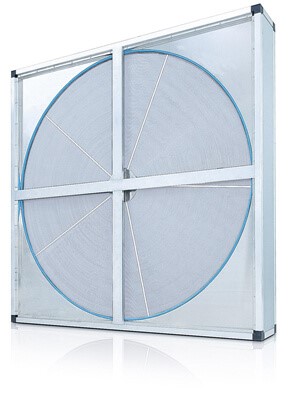
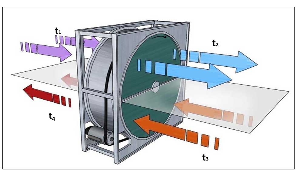
Heat Recovery Wheel is attached with fresh air handling unit or AHU so that it is divided into two half-moon section (see Fig.1 &2). When the enthalpy wheel is rotating, stale exhaust air (return air 24 °C) drawn through on half of wheel from building and outdoor air (fresh air 46 °C) passed through the other in a counter flow pattern. During this process the cooling is transfer from return air to fresh air. Which will reduce the fresh air temperature from 46 °C to 33 °C (see Fig.2), the temperature transfer depends on the effectiveness of the heat recovery wheel.

4. Performance of Heat Recovery Wheel

The wheel is designed to rotate between the outdoor and the return air streams of fresh air handling unit. It is entirely constructed with aluminum, the desiccant-coated aluminum filter supported with large spokes in thermal wheel. As the transfer core (enthalpy wheel) rotates between outdoor and return air streams, the sensible energy from higher temperature air stream is observed by aluminum fins. This energy is then transferred to the cooler air stream during the second half of the revolution as shown in fig.2).

The thermal wheel system is highly efficient (maximum up to 80%) compared to other heat recovery system.

The heat recovery system (HRS) is one of the key sustainable design systems that can be adopted especially in a hot climatic zone like Qatar to reduce the operational cost and environmental impact associated with air-conditioning.

Heat Recovery Wheel has higher effectiveness which eventually reduces the energy usage, capital cost and operational cost also reducing the environmental impacts.

5. Web based tool to calculate the Heat Recovery Performance

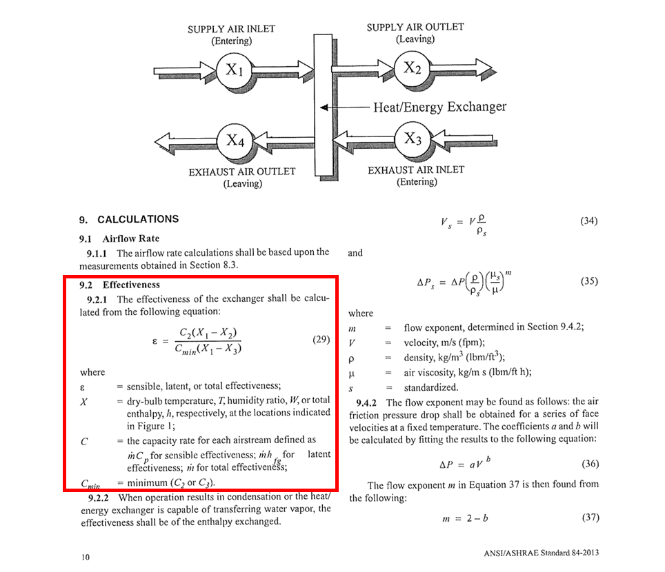
we have developed a calculation tool with minimal inputs which makes the interface of the tool user friendly. The tool is developed based on ASHRAE 84-2013 standard (See fig.3), considering inputs like Inlet air temperature, Outlet air temperature, air flow rates, etc.

The below fig.3 ASHRAE 84-2013 shows the equations for calculating the effectiveness of the exchanger which is formulated in this tool.

Fig.3 ASHRAE 84-2013

We have simplified the above equation from the ASHRAE 84-2013 in a much easier manner to make the readers understand in simpler way.

Fig.4 Heat Recovery Wheel Labelling

Effectiveness =  (V2 (t1-t2))/(Vmin (t1-t3))

Where,

t1 – Inlet supply fresh air DB temp (°C) (Atmospheric Air before Heat Exchanger)

t2 – Outlet Supply Fresh Air DB temp (°C) (Atmospheric Air after Heat Exchanger)

t3 – Inlet Exhaust Air DB temp (°C) (RA from building)

V1 – Supply Air Flow (L/s)

V2 – Exhaust Air Flow (L/s)

Vmin – Minimum of V1 , V2

The results for tool can be extracted and submitted as a design reports, specifications, material submittals, submissions to green building authorities, etc. Share your feedbacks/queries in the comments section below.

Conserve Solutions will be happy to assist your projects. Our offices are located in India, UAE, Qatar, Saudi Arabia, Canada, United Kingdom, Egypt and Singapore.

Author

Hameed Jasir K S M